Publication
Experimental investigation of vessel emission dispersion and exposure levels
S. Gillmeier; A. K.R. Jayakumari; E. W.M. Roosenboom; J. Muralha; G. Beleza Vaz; L. F. Sánchez Castro
How vessel exhaust reaches the working deck depends on much more than wind direction. Through controlled atmospheric boundary-layer wind-tunnel experiments, this study investigates how exhaust momentum, buoyant plume dynamics, vessel-induced wakes and operating conditions combine to determine pollutant concentrations and potential exposure levels on board an offshore service vessel.
Understanding vessel emissions at deck level
Air pollution from marine vessels is an environmental concern, but it is also an occupational safety issue. Crew members and offshore workers can be exposed to hazardous pollutants when exhaust emitted from a vessel's stack is transported back towards working areas on deck.
Predicting that exposure is complex. Exhaust dispersion is influenced not only by the surrounding wind, but also by the vessel's superstructure, the momentum and buoyancy of the exhaust plume, and the turbulent wake generated as air flows around the vessel.
Previous research has examined ship exhaust dispersion and vessel aerodynamics, but detailed experimental data on wake-dominated pollutant dispersion at vessel scale remains limited. Laboratory experiments also do not always reproduce buoyancy effects consistently with real-world conditions or translate measured concentrations into occupational exposure timescales.
This study addresses those gaps through controlled wind-tunnel experiments designed to reproduce the dominant physical processes governing vessel exhaust dispersion, while connecting measured pollutant concentrations with potential long and short-term exposure levels.
Recreating vessel emissions in the wind tunnel
The experiments were conducted in an Atmospheric Boundary Layer Wind Tunnel using a 1:100 scale model of a generic offshore service vessel, representative of vessels typically used for the construction and maintenance of offshore wind farms.
At full scale, the vessel represents a ship approximately 84 metres long and 17 metres wide, with an exhaust outlet located on the wheelhouse at a height of 20.2 metres above water level.
Neutral maritime atmospheric boundary-layer conditions were reproduced inside the tunnel. Rather than considering the exhaust plume as a simple passive tracer, the experiments were designed to reproduce its buoyancy behaviour by enforcing densimetric Froude number similarity between model and full scale.
A mixture of ethene, helium and synthetic air was released through the model exhaust. Ethene acted as the measurable tracer gas, while helium and synthetic air allowed the density of the model emissions to be controlled so that buoyancy-driven plume behaviour could be realistically represented.
25 locations across the vessel deck
Pollutant concentrations were measured at 25 locations across the vessel's deck, corresponding to a full-scale height of 1.5 metres above deck, representative of the breathing zone of crew and workers.
The study focused on three relative wind directions:
- 0° headwind;
- −15° oblique wind;
- +15° oblique wind from the opposite side.
The wider experimental campaign covered the complete 360° range in 15° increments, but these three conditions were selected for detailed analysis because they produce strong interactions between the exhaust plume, vessel wake and on-deck structures.
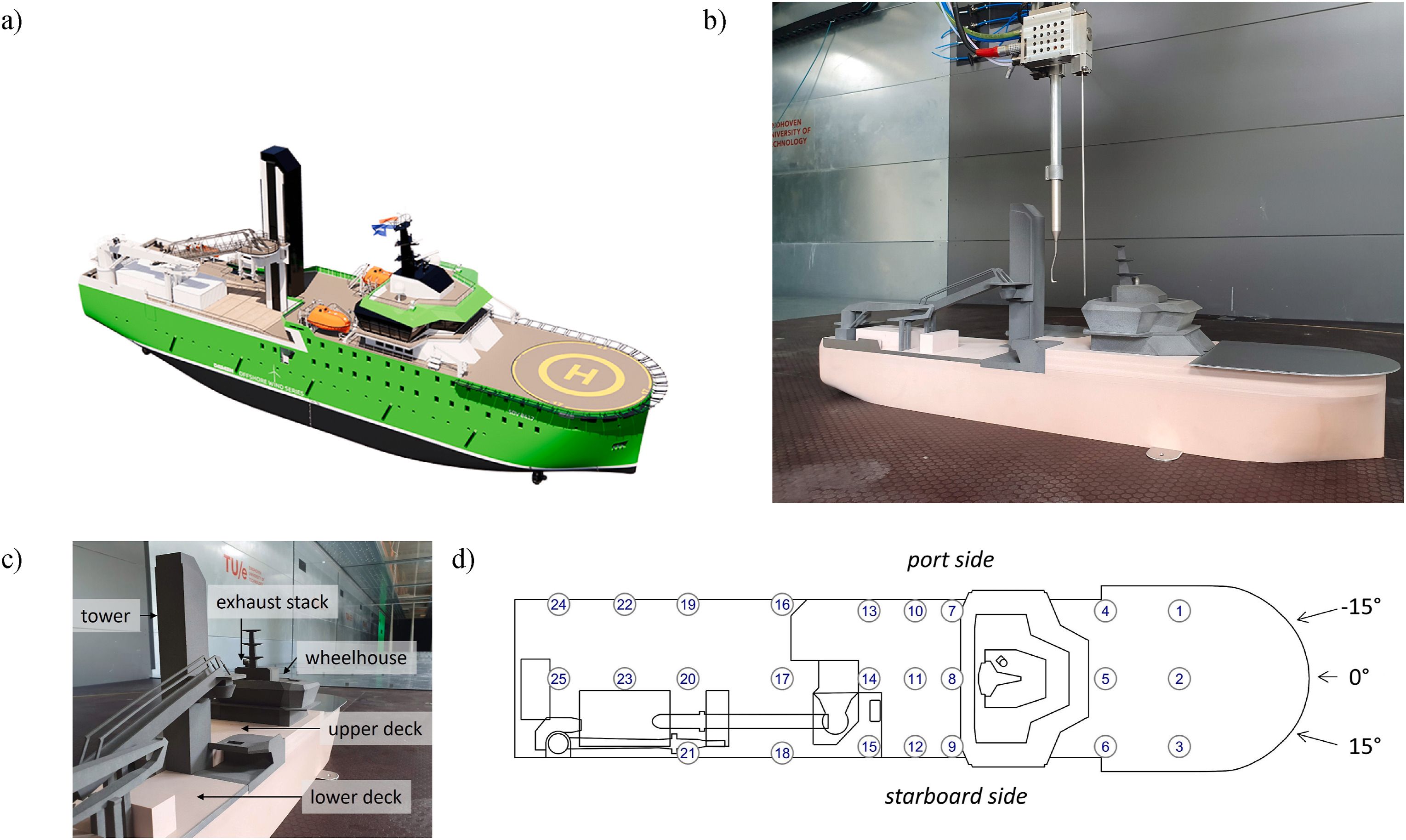
Illustrations of (a) an offshore service vessel and (b) the simplified and geometrically scaled vessel model. (c) Zoomed in view at the vessel model with indication of relevant deck components. (d) Measurement locations at zf = 1.5 m height above the vessel's deck, relative wind directions considered, and indication of port and starboard side.
When the vessel wake traps the exhaust
The experiments show that wind direction alone does not determine where pollutants accumulate.
Under headwind conditions, pollutants were detected at all measurement locations downstream of the exhaust. Flow separation behind the wheelhouse creates a negative-pressure wake region capable of drawing exhaust towards the deck.
The vessel's central tower further restricts ventilation in this area, creating a recirculation region where pollutants can remain trapped for longer periods. As a result, some of the highest concentrations occur between and downstream of major superstructure elements rather than simply along the expected wind direction.
The most critical wind direction
Of the three wind directions analysed, −15° produced the highest pollutant concentrations on deck.
Under this condition, the exhaust plume crosses the vessel and strongly interacts with the asymmetric wake created by the wheelhouse and other deck structures. This interaction pulls pollutants downward into areas occupied by crew.
Normalized concentrations reached 0.94% of the emitted concentration at locations on both the upper and lower decks.
By comparison, the +15° condition was considerably more favourable. Here, exhaust momentum and wind direction worked together to transport the plume away from the vessel before substantial interaction with the wake could occur. Across most measurement locations, concentrations remained below 0.06% of the emitted concentration.
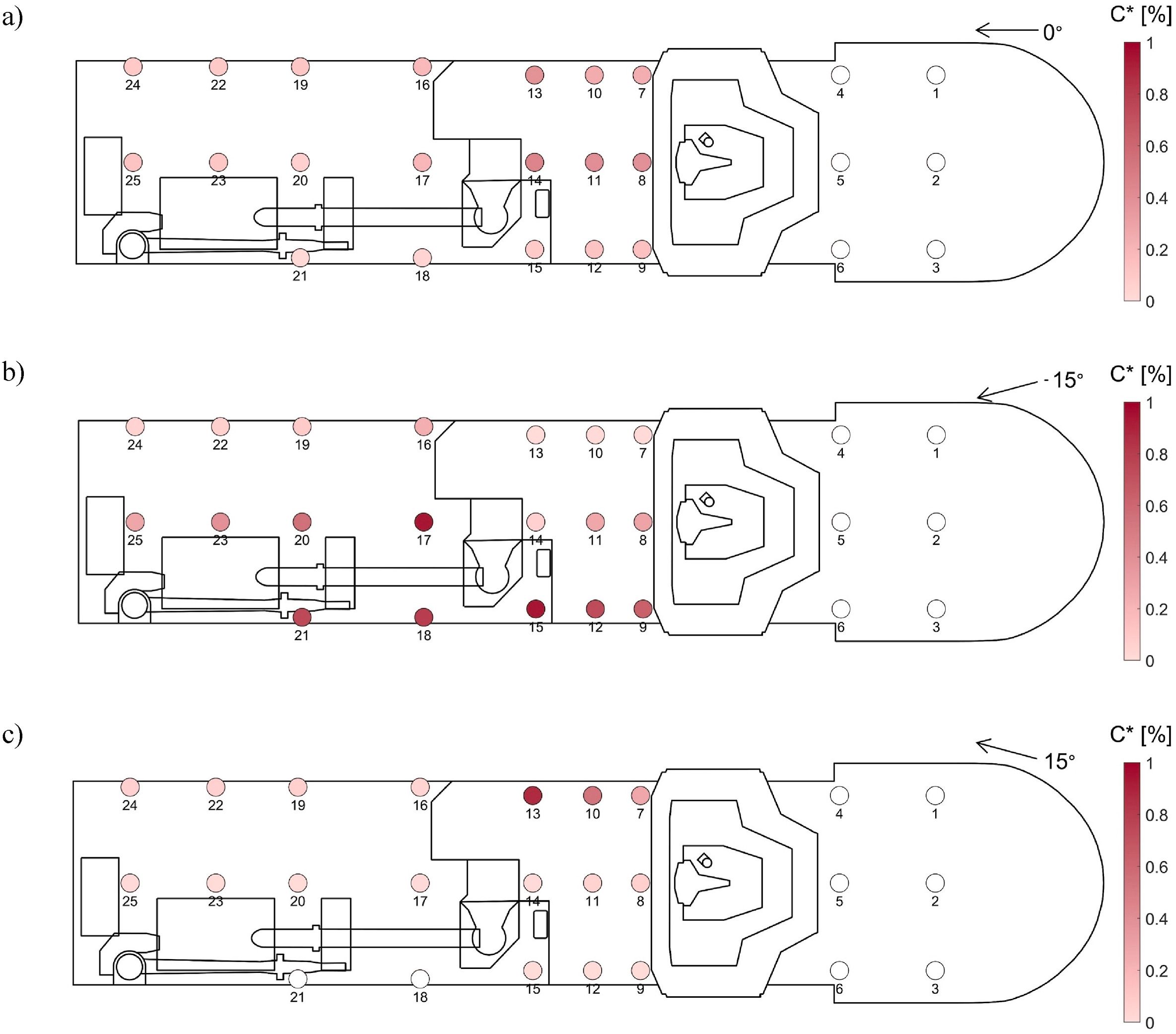
Time-averaged pollutant concentrations in percentage of released concentration at zf = 1.5 m height at indicated measurement locations on deck of the vessel for headwind (a), γ = − 15◦ (b) and γ = 15◦ (c).
Exhaust momentum can matter more than wind speed
The study also investigated what happens when ambient wind velocity and engine load change.
Doubling the reference wind speed from 10 m/s to 20 m/s had relatively little influence on concentrations across most of the vessel. Near-deck dispersion remained primarily controlled by recirculation zones and wake structures generated by the vessel geometry.
Engine load produced a very different result.
Increasing the engine load from 25% to 75% Maximum Continuous Rating (MCR) increased exhaust velocity from 8.8 m/s to 26.4 m/s. At the higher engine load, pollutant concentrations fell substantially across every measurement location, remaining below 0.04% of the emitted concentration.
The explanation lies in plume momentum.
At lower exhaust velocities, the plume does not have enough momentum to escape the recirculation region behind the wheelhouse and is more easily trapped within the vessel wake. At higher velocities, the exhaust jet has sufficient inertia to move beyond this region, carrying pollutants away from the vessel more effectively.
From pollutant dispersion to crew exposure
Measuring where exhaust travels is only part of the problem. The study goes further by translating experimental concentration measurements into potential occupational exposure levels, considering four hazardous gaseous components associated with marine diesel exhaust: carbon monoxide (CO), nitric oxide (NO), nitrogen dioxide (NO₂), and sulfur dioxide (SO₂).
The analysis distinguishes between long-term exposure limits (LTEL), generally based on an eight-hour working day, and short-term exposure limits (STEL), based on 15-minute average concentrations. The −15° wind direction was selected because it produced the most critical deck-level concentrations.
The results show that exposure can exceed occupational limits under unfavourable conditions and that fuel type and exhaust after-treatment can make a significant difference. Carbon monoxide remained below both long- and short-term exposure limits at every investigated location. NO, NO₂ and SO₂, however, could exceed occupational thresholds depending on fuel and exhaust treatment.
For untreated high-sulfur diesel, long-term SO₂ exposure reached approximately 15 times the exposure limit at the most affected locations. With exhaust after-treatment, this dropped to approximately three times the limit, while the number of locations exceeding the threshold also decreased substantially. For very-low-sulfur diesel, the SO₂ long-term exposure limit was maintained across all investigated locations, both with and without after-treatment.
Short-term exposure followed a similar pattern. Untreated NO reached a maximum exceedance factor of approximately 11, while exhaust after-treatment substantially reduced both the magnitude and number of exceedances. Very-low-sulfur diesel also kept SO₂ below its short-term exposure limit at all investigated locations.
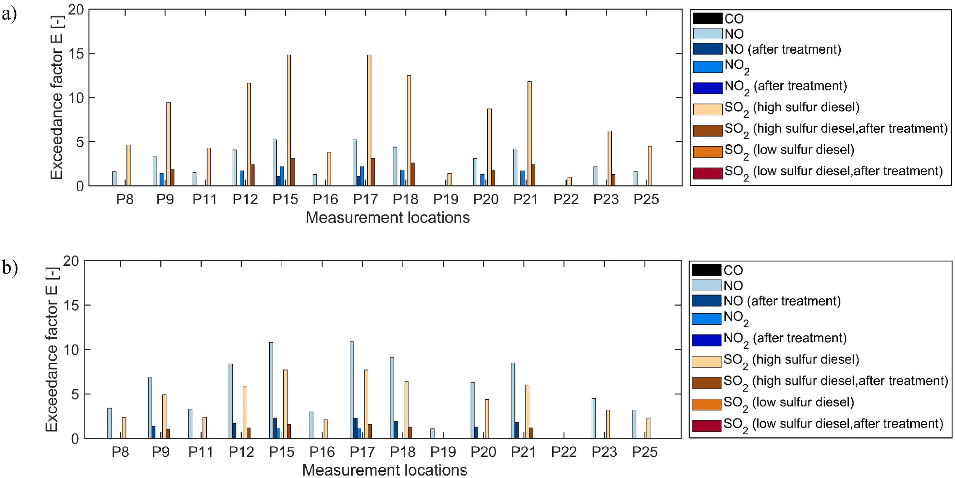
Long-term (a) and short-term (b) exposure value exceedance factors (E) investigated for γ = − 15◦ by considering the gas components CO, NO, NO2 and SO2.
Towards safer and more sustainable vessel design
The findings provide a physical basis for thinking about how vessel design could reduce crew exposure. Because pollutant accumulation is strongly connected to plume–wake interaction, mitigation should focus on preventing the exhaust plume from entering the vessel's main recirculation regions.
One possibility is repositioning the exhaust outlet above or outside these regions - for example, towards the top of the vessel's central tower, allowing the plume to disperse more effectively into the freestream.
Other potential approaches include flow-control devices such as deflectors or spoilers, as well as optimisation of exhaust outlet orientation and jet characteristics. These measures were not experimentally evaluated in this study, but the observed plume–wake mechanisms provide a basis for investigating them in future work.
This research was developed within POLISHED – Pollution, atmOspheric boundary Layers, Interaction and SHip Emission Data, a collaborative project involving Eindhoven University of Technology (TU/e), blueOASIS, DAMEN and KNUD E. HANSEN.
The full methodology, experimental results and exposure analysis are available in “Experimental investigation of vessel emission dispersion and exposure levels”, published in the Journal of Wind Engineering & Industrial Aerodynamics, Volume 278 (2026), Article 106617.
Partners

Related
Related Publications